


Correct installation of the Base pump
Preparing the Space in the Sump
To properly install the pump, it is crucial to first prepare the appropriate space in the sump. For this purpose, we need to consider the dimensions of the pump and ensure there is adequate space in the right area of the sump for the pump to operate freely. It is also important to consider the correct water level in the sump to prevent the pump from drawing in air.
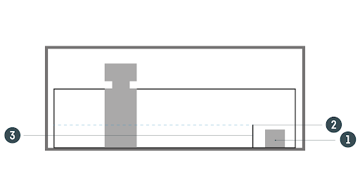
Below is a table with the dimensions of the Base Pump and the recommended dimensions for the sump chamber. The height of the sump chamber will correspond to the height of the partition as shown in the attached image.
PUMP MODEL | PUMP DIMENSIONS | MINIMUM SUMP CHAMBER DIMENSIONS | ||||
|---|---|---|---|---|---|---|
| Dimensions | Width | Length | Height | Width | Length | Height |
| Base pump 3000 | 7.5 cm [3 in] | 16 cm [6.3 in] | 10.5 cm [4.1 in] | 13 cm [5.1 in] | 21 cm [8.3 in] | 15 cm [5.9 in] |
| Base pump 5000 | 13 cm [5.1 in] | 20 cm [7.9 in] | 13 cm [5.1 in] | 18 cm [7.1 in] | 25 cm [9.8 in] | 20 cm [7.9 in] |
| Base pump 8000 | 13 cm [5.1 in] | 20 cm [7.9 in] | 13 cm [5.1 in] | 18 cm [7.1 in] | 25 cm [9.8 in] | 20 cm [7.9 in] |
| Base pump 10000 | 13 cm [5.1 in] | 20 cm [7.9 in] | 13 cm [5.1 in] | 18 cm [7.1 in] | 25 cm [9.8 in] | 20 cm [7.9 in] |
| Base pump 13000 | 13 cm [5.1 in] | 24 cm [9.4 in] | 16 cm [6.3 in] | 20 cm [7.9 in] | 30 cm [11.8 in] | 22 cm [8.7 in] |
The attached diagram shows a partition (3) that affects the water level during the operation of the pump (2). The recommended minimum heights for the sump chamber dimensions are consistent with the dimensions marked on the diagram below with number 2. At lower water heights, the pump can generate noise and become air-bound during suction.
Automatic Top-Off System
For the proper operation of a circulation pump, it’s essential to automatically replenish water that evaporates. This is crucial for maintaining a constant water level in the tank. As water evaporates, the level in the pump chamber decreases, which can lead to the pump drawing in air. To prevent this, the use of an automatic water top-off system is recommended. In this case, we recommend the Dosing Pump ATO or Level Keeper devices.
Assembling the Pump
The next step is to assemble the pump. Most of the pump parts should already be in place. Just check to ensure nothing is missing and purchase any necessary missing components. Don’t forget to install the rubber feet which help reduce noise levels.

In the image above, you can see the components that need to be connected. For more details, refer to the user manual: here.
Preparing the Plumbing
Instructions on how to glue the plumbing can be found in these articles:
- Practical Understanding of Hydraulics in a Marine Aquarium
- How to Connect Hydraulics in a Saltwater Aquarium
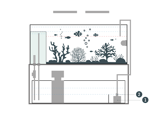
The pump should be placed in the location marked with the number 2 on the diagram above. It is recommended to first perform a “dry fit” without using glue and then after carefully aligning all components, proceed to glue the parts together directly in the sump.
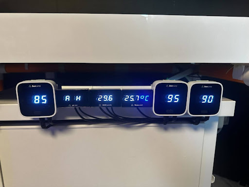
Controller and Power Supply Installation
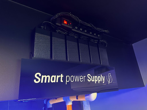
The controller should be installed in a way that makes it easily accessible and visible, taking into account the length of the cable. The power supply should be placed in a location protected from flooding. Additionally, it’s important to ensure that the cables are neatly arranged.
Summary
If all steps have been executed correctly, congratulations – the pump is properly installed. After the plumbing has had time to dry, you can begin operating the pump.